How To Replace A Failed Power Supply Capacitors And Revive A Dead Bluesound Node 2 Streamer
The Bluesound Node 2 is an awesome music streamer… when it works. Unfortunately, some of the units are doomed to a short lifespan after capacitor failure within the unit’s power supply. Here’s how to fix it.
Bluesound Node 2 power supply showing the two green and white power supply electrolytic capacitors that fail in these units (right center of the board).
The Bluesound Node 2 dreaded solid red light; a story of early capacitor failure
In 2017 I bought a handful of Bluesound Node 2 streamers for our home multi-room audio system. A few years later, one by one, the players stopped working and displayed a solid red indicator light. Nothing I tried could bring the units back to life.
Finally, I stumbled on a post suggesting that failed capacitors in the Node 2 power supply may be the reason for the dreaded Bluesound Node 2 red-light perma-nap. I decided to open one up to have a look.
After opening a unit, I could see what looked like two bad capacitors on the power supply board. Both of the capacitors near the left center of the board had bowed residue-stained caps. Cool! This could be an easy DIY fix, and the cost of the two replacement capacitors are less than a cup of coffee!
I fixed my Node2 player by swapping out two power supply capacitors
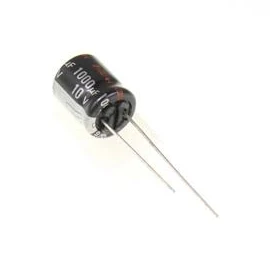
I ordered replacement capacitors (Panasonic 10v 1,000µF) swapped them for the dead ones. And what do you know, just like that, my Node 2s came back to life.
Although these power units have a handful of electrolytic capacitors, I would guess most of the failures involve these two capacitors.
Just to be safe, I ordered replacements for all of the capacitors in the power supply, thanks to this post and capacitor list at thread on the HiFi Haeven forum. Thanks to janihy and HiFi Haeven for the thread and parts list.
Although I originally ordered and used the Panasonic FR series capacitors listed below, I later ordered the same capacitors in the Panasonic FM series (and a few other manufacturers) just for fun to see if I noticed any sound difference. I did notice a difference in sound, and ended up using the FM series capacitors for most of my units (see below).
A list of the Node 2 power supply electrolytic capacitors in the Panasonic FR series capacitors (low ESR, long life) available for immediate shipping at Mouser:
3x Panasonic EEU-FR1A102B 1000µF, 10V, 20%, 105℃
1x Panasonic EEU-FR1A101 100µF, 10V, 20%, 105℃
1x Panasonic EEU-FR1A152LB 1500µF, 10V, 20%, 105℃
1x Panasonic EEU-FR1E470 47µF, 25V, 20%, 105℃
3x Panasonic EEU-FR1H100B 10F, 50V, 20%, 105℃
1x Panasonic EEU-ED2G100 10µF, 400V, 20%, 105℃
1x Panasonic EEU-ED2G220 22µF, 400V, 20%, 105℃
Should you replace all of the power supply capacitors or just the two that usually fail?
I have a total of ten Bluesound Node 2 units. Six of the ten stopped working. All of the six units worked again after just replacing the two 1000µF, 10V capacitors (capacitors C11, C12 on the power board).
With the unit open, it might make sense to replace all of them. For me, I was happy to get the units working again, and if they fail down the road, I can always do a wholesale replacement then.
Are some electrolytic capacitors better than others for the replacement in the Bluesound Node 2 power supply
I don’t know for sure, but I was curious. Aside from using high-quality high-temperature long service life capacitors, do some actually sound better than others in the Node 2 units? I was curious, and ordered a few different capacitors to do a sound comparison.
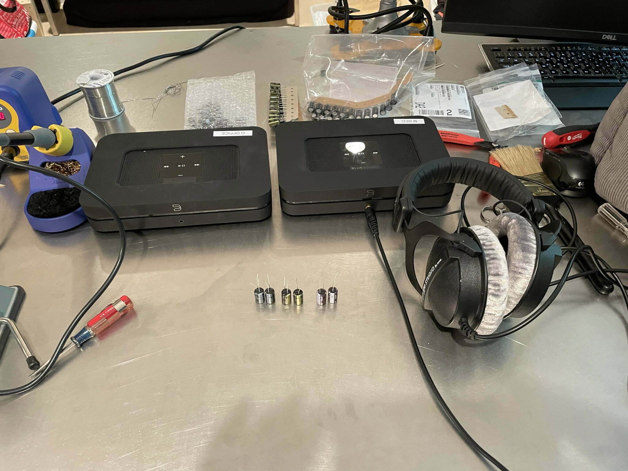
I compared the different capacitors doing a rather informal A/B comparison test using headphones through the front headphone jack of two linked units playing the same music track at the same volume.
I used three different capacitors that were in stock at Mouser.com that I could get in a few days. The three different capacitors are:
Panasonic FR series (EEU-FR1A102) 1000µF, 10V, 20%, 105℃, 8,000 hour life, radial lead, 5mm lead spacing, 10mm x 16mm dimensions
Panasonic FM series (EEU-FM1A102B) 1000µF, 10V, 20%, 105℃, 4,000 hour life, radial lead, 5mm lead spacing, 10mm x 16mm dimensions
Nichicon UPW series (UPW1A102MPD) 1000µF, 10V, 20%, 105℃, 5,000 hour life, radial lead, 5mm lead spacing, 10mm x 16mm dimensions
These are my impressions of the sound of the three different capacitors in the Node2 unit:
Panasonic FR series: neutral, flat, reasonable bass and treble
Panasonic FM series: dynamic, thicker bass, sharper treble, better presence
Nichicon UPW series: warm, good definition, pleasant bass and treble
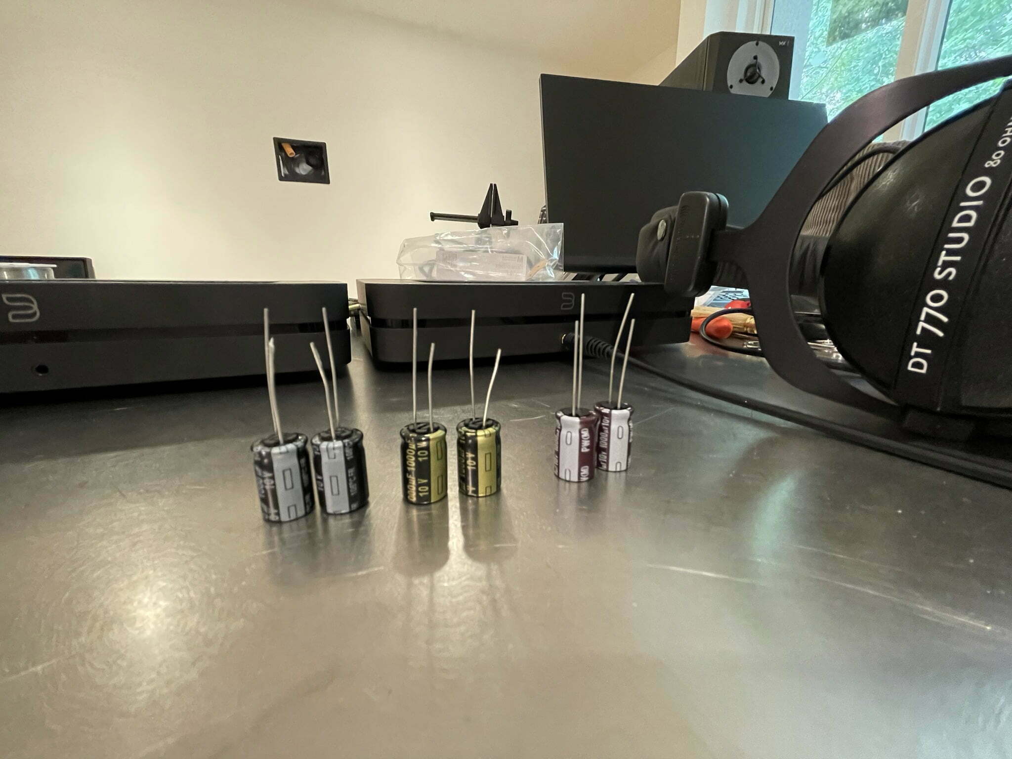
Three different 1,000 uF, 10V electrolytic capacitors left to right: Panasonic FR series, Panasonic FM series and the Nichicon UPW series.
I choose the Panasonic FM series for most of the players. I used the Nichicon UPW series capacitors in a few of the players. I think they all sounded good. My headphone listening drew me toward the brighter Panasonic FM series, but after listening to the system through our in-ceiling speakers, they may be a tad bright and I may have preferred the Nichicon.
I also realize that the sound of the units may change or mellow when the capacitors age a bit. It was easy enough to replace the capacitors, so I could always change them in the future. I’m curious to hear what those with expertise in the field would say about break-in, and the sound differences of power supply capacitors.
All of the above listening impressions come with the large disclosure that the test was far from a profession comparison.
I do think they all sounded somewhat different and consistently chose the Panasonic FM series capacitors despite not knowing which units had which capacitors installed.
I find it interesting that just replacing those two capacitors, which the remaining the factory originals, could alter my perception of the sound output.
A/B listening comparison of the three different capacitors in the Node 2 player; Panasonic FR series sounded neutral, the FM series sounded dynamic and bright and the Nichicon UPW series sounded warm and natural.
Overview | Node2 Capacitor Replacement
Project Goal: To restore function of the Bluesound Node 2 player by replacing failed power supply capacitors.
Open the Node 2 player, inspect the power supply capacitors.
Work in a static-free environment, avoiding carpet, rugs, static-generating clothing, and socks. Ground yourself to discharge electrostatic charge. Consider using an electrostatic discharge (ESD) mat and an ESD wrist strap. Avoid breathing solder fumes by using a fume extractor or small fan in a well-ventilated area. Wear an N95 mask or respirator designed for soldering and welding.
OK, on to the fun...
Disconnect the AC power plug at the rear of the unit. Lift off the rear metal plate with a small flat blade or screwdriver. This plate is magnetically attached. Remove the four black corner case screws and two chrome screws flanking the AC input.
After the screws are removed, gently separate the top and bottom sections of the unit. The front of the unit is connected by plastic interlocking tabs that will separate with gentle force. Next, start separating the case at the rear and gently open the case like a book until the front tabs disengage. A sharp click is generated when the front case tabs are separated. Use care not to stretch or damage the two wires connected to the top of the case.
Inspect the power supply, focusing attention on the two larger green/white capacitors located at the center, left side of the board adjacent to a black metal heat sink. These are the two capacitors of interest, which are often responsible for the power unit failure. Inspect these capacitors closely for signs of failure, including; a budging proud top cap, signs of electrolyte seepage, or other signs of physical damage.
Notice how these two capacitors on my unit's power supply are budging upward slightly and have a slight residue suggesting an electrolyte leak at the top. These capacitors are dead and need to be replaced. I suspect the location of the capacitors very near what appears to be a warm area of the power supply is partly to blame for their failure.
While other capacitors may also have failed or are failing, these two seem to represent most of the problems in these power supplies. So, in addition to replacing these capacitors, some do a whole replacement of all of the capacitors in the power supply for good measure. Not a bad idea, especially if you feel confident in your soldering skills compared to the risks of damaging something on the board while replacing all the capacitors.
For this unit, I was happy just replacing the two bad capacitors.
Remove the power supply board from the Node2.
Locate the power supply located at the right of the unit when viewed from the rear. Next, remove the power supply board by unscrewing the four chrome corner mounting screws of the board. The two screws at the back of the board also hold a small metal bracket that spans the AC power input.
Next, release the two wire harnesses connecting the power supply to the main board of the unit. Use needle-nose pliers or a small flat screwdriver to remove the connectors as needed gently. Finally, lift the power supply from the unit.
Locate and remove the failed capacitors.
Locate the failed capacitors and any other capacitors you plan to replace. For example, some capacitors are secured to the circuit board with glue that may need to be removed before removing the capacitors.
Before removing the capacitors, note the capacitor's polarity and its' orientation on the circuit board. Often the negative lead of the capacitor is marked with a white strip down the side of the capacitor body. This negative side or lead is typically noted on the circuit board with a negative symbol. Some mark the top of the capacitor on the rear or front-facing side of the capacitor for reference before removing them.
Once you locate the capacitors to be replaced, flip the board and note the location of the soldered leads of the capacitors of interest. Then, using a fine tip soldering iron, heat the solder holding the leads of the capacitor. Once the solder liquefies, tip the capacitor side-to-side to pull the leads out of the circuit board.
The tight location of the two capacitors near the heat sink makes it challenging to access the capacitors limited your ability to manipulate them using your fingers. So instead, I used a small flat screwdriver gently wedged underneath the base of the capacitors to free them while heating the solder.
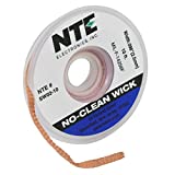
After removing the capacitors, desolder the capacitor lead through holes on the circuit board to make it easier to install the new capacitors. There are a few ways to remove the old solder from the through-holes. I used desoldering wick and a toothpick. Desoldering suction devices also work well, but I didn't have one for this project.
To desolder with wick material, place a clean end of the wick over the solder-filled holes and carefully apply heat on the wick directly over the solder to be removed. Once the solder liquefies, it will move off the circuit board and into the wick.
Then, use a toothpick if needed to clean the through-hole of residual solder by heating the hole on the bottom of the board while gently pushing the toothpick through the top of the board. When the solder softens, the toothpick will pass through the hole, cleaning it.
Install the new replacement capacitors.
After removing the old capacitors, replace them with new, compatible capacitors of the same capacitance, voltage, size, lead size, and service life. There are many choices for replacement capacitors. I suggest using components from a top-tier maker like Panasonic, Nichicon, Rubycon, United Chemi-Con, and a few others.
I used Panasonic capacitors ordered from Mouser Electronics (mouser.com). Select a capacitor with the same specs as the originals and choose capacitors with 105-degree temperature ratings and long service life ratings if possible. The location of the two failed capacitors is likely a hot, demanding location for capacitors.
Install the replacement capacitors in the same polarity orientation as the originals. In addition, the negative lead should be marked on the new capacitor.
With the new capacitor leads in proper polarity orientation, pass the leads through the circuit board through holes. Next, press down to hold the capacitor against the board and then turn the board over and slightly bend and spread the capacitor leads outward to have the capacitor in position until the leads are soldered in place. Then solder the leads from the bottom of the board.
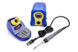
To solder the leads, first heat the soldering iron. I have the Hakko Soldering Station, which I highly recommend. It displays the temperature of the soldering iron tip so you know when it is up to heat. It also heats up very quickly and is a joy to use. The soldering iron holder is super solid and firmly holds the iron when it is not in use.
If you have control of the temperature of your soldering iron, start with a temperature of 315°C (600°F) to 400°C (750°F) depending on the type of solder you are using.
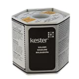
Once the soldering iron is up to temperature, clean the tip using a damp sponge or tip cleaning metal mesh. After cleaning, tin the tip by touching the soldering iron tip with solder. Now move the soldering iron to the base of the capacitor lead at the board. Next, place the soldering iron tip at the base of the capacitor lead as it exits the through-hole on the circuit board. Hold the tip in place for a second or so, then touch the end of the solder (I use Kester yellow label .05" diameter) to the lead and hole on the side opposite of the soldering iron. If the lead and through-hole are sufficiently hot, the solder will melt and flow smoothly into the through-hole and wick up the capacitor lead.
A good soldier should be smooth, slightly shiny, and flow through the through-hole to the opposite side of the board. Use care not to apply too much heat to the circuit board or component lead, which can damage the circuit board or component being installed. Also, be aware of circuit components adjacent to or near the area you are soldering (or desoldering), taking care to avoid applying heat to these unintended targets.
Give the solder joint 30 seconds to harden, then cut the leads off just above the solder joint.
Reassemble the Node2 and test the operation of the unit.
Replace the power supply board within the unit and replace the mounting screws and small bracket around the AC power input. Re-attach the two power lead connectors on the mainboard.
Place the black plastic rear plate with the magnets mounted on it back on the back of the bottom tray of the Node 2. Close the Node 2 case starting at the front of the case. Align the tabs and notches of the top and bottom halves and press together firmly to connect. Be careful not to pinch, kink, or trap the two wires connected between the top and bottom cases.
Close the back of the case bring the top and bottom halves together. Replace the rear corner case screws and the two chrome screws on either side of the AC power input. Remount the back metal magnetic mount faceplate.
After the unit is back together, plug it in and check for proper operation. At first, the red light will display, followed by a flashing green light and a solid blue light indicating the unit is ready for use!
Just adding my thanks. Very clear instructions and having the parts list made it that much simpler. Unit is working again.
I have a Vault2 in the same ‘solid red’ state. I saw a couple of mentions of Vaults on this thread, but has anyone repaired their Vault or even know if the power supply board and components are the same? This is promising news for my situation.
Had the same problem on a 5 year + Node 2 , but the caps looked perfect to me. I ruled out firmware with Bluesound support, and replaced the caps anyway.
And it worked!
Thanks a lot G Zup,
This has worked brilliantly. Your explanations are so clear and so detailed. You made my day, did something for the planet and my self esteem at the same time.
I went for the Nichicon, after a brief first listening, it clearly has an impact on the sound. I am still figuring out whether this is better or worse…deeper bass, and clearer treble at the same time. Anyway.
Thanks again
Brilliant writeup! Swapped the 2 caps with longer life Panny FRs and it powered right up. The rest of the caps are glued down so leaving them alone. Thanks for this.
I have to thank you, for the detailed information.
I use node and vault from bluesound.
Both use the same manufactory (KSC) and in both the caps can and will fail.
ATTENTION: also the smaller caps are often low on capacity!
I measured them and I was shocked ,often only 1/3 of capacity left.
Regards
Oliver from Germany
Brilliant, you saved me £600 by advising of the C11&C12 fix, which worked a dream and cost me £5 for capacitors and £12 for a fine tipped soldering iron.
Brilliant, you saved me £600 by advising of the C11&C12 fix, which worked a dream and cost me £5 for capacitors and £12 for a fine tipped soldering iron. Fantastic.
Anyone with solid red Led. Don’t hesitate, replace C11 & C12.
Hi Robert, glad the article helped! Sorry for the late reply.
Great post! You saved my Node
Thank you very much
Thanks Farbrizio!
Thank you for taking the time to post this, I followed your instructions easily and even as a complete amatuer managed to get my node back up and running, you saved me a fortune. Thanks again, Rob.
Worked perfectly, even with no electrical experience as your instructions were so good, Thank you so much!
You are welcome Robert, glad you were able to fix it.
Wow! What a great tutorial with detailed explanations and helpful pictures!
I only had to change one capacitor before the Bluesound was up and working again.
Thanks for your effort with posting this FIX, you have saved me a lot of bucks.
If you ever visit Denmark, I will buy you a beer!
Hey Jens, thanks for the comments and beer credit!
Thanks a lot!
Worked like a charm. Node 2 up and running again!
Thank you very much, very good description!
My Node 2 had the same problem with the solid red error.
I just changed the 2 1000yF Elkos and – it works again.
🙂
Greetings Rolf
Awesome!
Thanks a lot for all the detailed procedure, it worked on my unit.
Hello, i´am owning two Node 2. One of them is still Running. The second Node 2 is out of order ( red ligbt death)
I changed the Power supply from number one (still running Node) to the second Node. But the failed Node 2 will not work.
So i know it can´t be the Power Supply. What could it ne? Have someone another idea? What is failed in the second Node?
Thanks forward Martin
Thanks a lot for your great post. Such an easy fix. For just a couple of Euro’s i have a great working Node again.
Thanks a lot 🙏
You are welcome. Thanks for the comments Bas!
I replaced the two capacitors EEU-FR1A102B, and it seemed to work a bit better. Before, the light on ethernet was constant. Now it is blinking when receive transmit data, however, it is still stuck in red. I replaced a couple of the other capacitors, but still no luck. The remaining capacitors looks good.
It fixed my Node2. Thank you!
Dear Sirs,
Could you please send me the full resolution picture of “de-solder-wick-to-remove-excess-solder-bluesound-node2.jpeg”?
Or send me the text written on the following parts?
I have a blown PSU and the following parts cannot be read: R34, R37, R38.
Thank you so much!
Great post. Trying to get a Vault2 to have power. No red light or anything. Replaced many caps. Ideas?
I have a PSU board with a view burnt components
Are there schematics available so i can look up the resistor values ?
Your fix saved me about $600! I had the same problem even though my caps still looked ok, measuring one proofed to only be 500uF.
After replacing the two suspects my Node 1 is working perfectly again.
Thank you!
Thanks for the post. I have a failed Node 2 with the same two capacitors looking swollen. Replaced them, but unfortunately no luck for me. Same behavior: solid red.
Update: just replaced the two offending capacitors from your list (Nichicon).
Very simple task.
Now up and running again.
Thanks so much .
Update: just replaced the two offending capacitors from your list (Nichicon).
Very simple task.
Now up and running again.
Thanks so much for a great article.
Fantastic article, very detailed and helpful.
I shall be giving this a try as my node 2 has just expired, along with many others I gather.
Update: just replaced the two offending capacitors from your list (Nichicon).
Very simple task.
Now up and running again.
Thanks so much .


Thank you. Saved me a lot of money.
Hey Kent,
I’m glad it worked for you too.
Just adding my thanks. Very clear instructions and having the parts list made it that much simpler. Unit is working again.
I have a Vault2 in the same ‘solid red’ state. I saw a couple of mentions of Vaults on this thread, but has anyone repaired their Vault or even know if the power supply board and components are the same? This is promising news for my situation.
Had the same problem on a 5 year + Node 2 , but the caps looked perfect to me. I ruled out firmware with Bluesound support, and replaced the caps anyway.
And it worked!
Thanks a lot G Zup,
This has worked brilliantly. Your explanations are so clear and so detailed. You made my day, did something for the planet and my self esteem at the same time.
I went for the Nichicon, after a brief first listening, it clearly has an impact on the sound. I am still figuring out whether this is better or worse…deeper bass, and clearer treble at the same time. Anyway.
Thanks again
Brilliant writeup! Swapped the 2 caps with longer life Panny FRs and it powered right up. The rest of the caps are glued down so leaving them alone. Thanks for this.
I have to thank you, for the detailed information.
I use node and vault from bluesound.
Both use the same manufactory (KSC) and in both the caps can and will fail.
ATTENTION: also the smaller caps are often low on capacity!
I measured them and I was shocked ,often only 1/3 of capacity left.
Regards
Oliver from Germany
Brilliant, you saved me £600 by advising of the C11&C12 fix, which worked a dream and cost me £5 for capacitors and £12 for a fine tipped soldering iron.
Brilliant, you saved me £600 by advising of the C11&C12 fix, which worked a dream and cost me £5 for capacitors and £12 for a fine tipped soldering iron. Fantastic.
Anyone with solid red Led. Don’t hesitate, replace C11 & C12.
Hi Robert, glad the article helped! Sorry for the late reply.
Great post! You saved my Node
Thank you very much
Thanks Farbrizio!
Thank you for taking the time to post this, I followed your instructions easily and even as a complete amatuer managed to get my node back up and running, you saved me a fortune. Thanks again, Rob.
Worked perfectly, even with no electrical experience as your instructions were so good, Thank you so much!
You are welcome Robert, glad you were able to fix it.
Wow! What a great tutorial with detailed explanations and helpful pictures!
I only had to change one capacitor before the Bluesound was up and working again.
Thanks for your effort with posting this FIX, you have saved me a lot of bucks.
If you ever visit Denmark, I will buy you a beer!
Hey Jens, thanks for the comments and beer credit!
Thanks a lot!
Worked like a charm. Node 2 up and running again!
Thank you very much, very good description!
My Node 2 had the same problem with the solid red error.
I just changed the 2 1000yF Elkos and – it works again.
🙂
Greetings Rolf
Awesome!
Thanks a lot for all the detailed procedure, it worked on my unit.
Hello, i´am owning two Node 2. One of them is still Running. The second Node 2 is out of order ( red ligbt death)
I changed the Power supply from number one (still running Node) to the second Node. But the failed Node 2 will not work.
So i know it can´t be the Power Supply. What could it ne? Have someone another idea? What is failed in the second Node?
Thanks forward Martin
Thanks a lot for your great post. Such an easy fix. For just a couple of Euro’s i have a great working Node again.
Thanks a lot 🙏
You are welcome. Thanks for the comments Bas!
I replaced the two capacitors EEU-FR1A102B, and it seemed to work a bit better. Before, the light on ethernet was constant. Now it is blinking when receive transmit data, however, it is still stuck in red. I replaced a couple of the other capacitors, but still no luck. The remaining capacitors looks good.
It fixed my Node2. Thank you!
Dear Sirs,
Could you please send me the full resolution picture of “de-solder-wick-to-remove-excess-solder-bluesound-node2.jpeg”?
Or send me the text written on the following parts?
I have a blown PSU and the following parts cannot be read: R34, R37, R38.
Thank you so much!
Great post. Trying to get a Vault2 to have power. No red light or anything. Replaced many caps. Ideas?
I have a PSU board with a view burnt components
Are there schematics available so i can look up the resistor values ?
Your fix saved me about $600! I had the same problem even though my caps still looked ok, measuring one proofed to only be 500uF.
After replacing the two suspects my Node 1 is working perfectly again.
Thank you!
Thanks for the post. I have a failed Node 2 with the same two capacitors looking swollen. Replaced them, but unfortunately no luck for me. Same behavior: solid red.
Update: just replaced the two offending capacitors from your list (Nichicon).
Very simple task.
Now up and running again.
Thanks so much .
Update: just replaced the two offending capacitors from your list (Nichicon).
Very simple task.
Now up and running again.
Thanks so much for a great article.
Fantastic article, very detailed and helpful.
I shall be giving this a try as my node 2 has just expired, along with many others I gather.
Update: just replaced the two offending capacitors from your list (Nichicon).
Very simple task.
Now up and running again.
Thanks so much .